







About Bizwheel
The main component of a healthy environment for self esteem is that it needs be nurturing. It should provide unconditional warmth.
We offer phase ampere meter and volt meter with and without built-in selector switches to meet multiple requirements of our clients. We also provide stand-alone meters like KW, PF, Frequency, Hz.

Infinity and Entity from Trinity are digital energy meters for use in three phase electrical systems for sub-metering applications.
The design of these meters is based on proven microcontroller technology; with front end ASICs resulting in compact and accurate energy metering. The accuracy of the meters is maintained even under severely distorted waveform conditions which occur due to harmonics in the system.
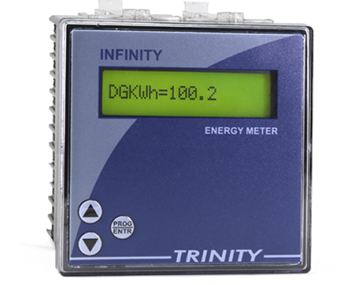
Infinity and Entity from Trinity are digital energy meters for use in three phase electrical systems for sub-metering applications.
The design of these meters is based on proven microcontroller technology; with front end ASICs resulting in compact and accurate energy metering. The accuracy of the meters is maintained even under severely distorted waveform conditions which occur due to harmonics in the system.
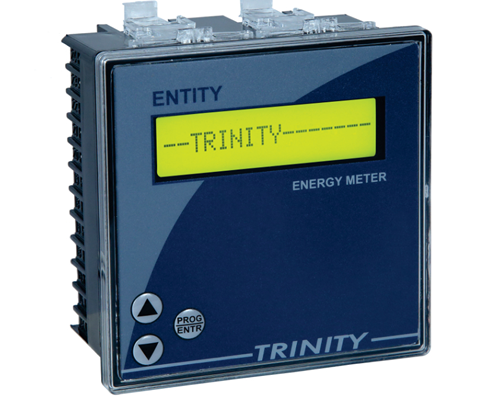
The VAF model meters from Trinity are True RMS type digital meters for use in three phase four wire LT electrical systems. The design of these meters is based on proven micro-controller technology, resulting in compact and accurate meters. The design uses powerful micro-controller based technology. The meter uses state of the art Digital Signal Processing (DSP) circuitry to achieve very high accuracy measurement of True RMS value of all parameters. The meter displays the readings on Crisp Super bright LED Displays.
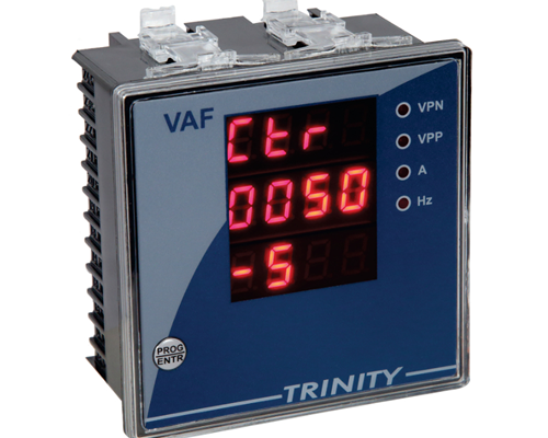
The most versatile and intelligent Multifunction meter for measuring all the basic electrical parameters along with energy and power.

The unit is low cost, easy-to-use, individual and multifunctional that enables to measure all the basic parameters required in an electrical installation and monitors electricity over and above basic metering. The entire range is very rugged and cost-effective. All these products are field proven and more than 100,000 units are active in service.

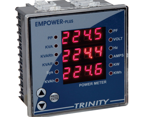
The Empower Plus from Trinity is an easy-to-use, cost effective electrical power meter that offers all the basic measurement capabilities required to monitor an electrical installation. In addition to measuring the instantaneous parameters, it also measures all three energies, thus helping to measure energy costs. Over the basic metering, it provides RS485 port supporting MODBUS RTU protocol, THD measurements, Phase angle, Unbalance % for Voltage and Current, On Hour & Run Hour, Power Interruption recording. These parameters are available over RS485 only. The CT Primary, Secondary and PT ratios are site selectable.
BMM (Blind Measuring Module) is multi functional unit which supports only 3P4W installation. BMM take 3 Voltage inputs & 3 Amps inputs for measurement. BMM measures phase wise Voltage, Amps, PF, Power as well as System Power, Energy, Frequency. For demand calculation BMM has Fixed 30 Minute window, based on Real Time Clock for KW as well as KVA. BMM provides one RS485 port with Modbus-RTU protocol to communicate with external world. As BMM receive any data over RS485 then “RxD” led will glow and if BMM is responding over RS485 then “TxD” led will glow. As unit power up, “POWER” led glows. BMM provides pulse on led (1000 Pulse/KWh) as well as on isolated opto coupler.

| Parameters | |||
|---|---|---|---|
| Type | Name | Statistics | |
| Input | Supply | Three Phases and Neutral of a 3P4W system | |
| Voltage | Direct Voltage Input : Up to 300V L-N PT Ratio : 1 Burden : 1 VA |
||
| Current | Secondary Current Input: - - CT Ratio : 1 Range of Reading : up to 70 Amps Burden : < 1.0VA Overload : 75A RMS Continuous |
||
| PowerSupply | Auxiliary Supply: 90 - 270 VAC (P-N), 50-60 Hz. (Power Up from 3 Phase Voltage Input) | ||
| MEASUREMENT | True RMSBasicParameters | Voltage(Volts L-N & L-L) | VL-N Accuracy : 0.5% of Reading VL-L Accuracy : 1.0% of Reading |
| Current(Amps IR, IY, IB) | Accuracy : 1% of Reading | ||
| Line Frequency | 46.5 to 63.5 Hz, Accuracy : 0.3% of Reading | ||
| Power | Active Power (P) | Accuracy : 1% of Reading(For IPFI>0.5) | |
| Reactive Power (Q) | Accuracy : 1.5% of Reading(Between 0.5 Lag to 0.8 Lead) | ||
| Apparent Power (S) | Accuracy : 1% of Reading | ||
| Power Factor | For Individual phases and System. Accuracy : 1.0% of Reading (IPFI≥0.5) Range of Reading : 0.05 to 1.00 Lag/Lead |
||
| Energy | Total Active Energy (KWh) | Range of Reading : 0 to 9999999.9 KWh Accuracy : Class 1 as per IS13779 |
|
| Total Apparent Energy (KVAh) | Range of Reading : 0 to 9999999.9 KVAh Accuracy : Class 1 |
||
| Total Apparent Energy (KVARh) | Range of Reading : 0 to 9999999.9 KVARh Accuracy : Class 1 |
||
| Demand | Active Power (KW) Demand – 30 Minute Fixed Window | ||
| Apparent Power (KVA) Demand - 30 Minute Fixed Window | |||
SLM-PRO

The Power Pro from Trinity is an easy-to-use, cost effective electrical power meter that offers all the basic measurement capabilities required to monitor an electrical installation. In addition to measuring the instantaneous parameters, it also measures accurately all three energies, and also demand, thus helping to measure and control energy costs.
Over the basic metering, it optionally provides two relay outputs, RS485 port supporting MODBUS RTU protocol, dual source metering and THD measurements.
The relays are site programmable for parameter of action, and the value on which to operate.
The CT primary and secondary, PT ratio and installation type are site selectable, thus making it possible to use the meter in all types of three phase installations.

| Parameter | |||
|---|---|---|---|
| Type | Name | Statistics | |
| Input | Supply | Three Phases and Neutral of a 3P4W system / Three Phases of a 3P3W system | |
| Voltage | Direct Voltage Input : Up to 500V L-L, Up to 300V L-N PT Ratio: Site Selectable Burden: 0.5VA |
||
| Current | Secondary Current Input: 5A or 1A (Site Selectable) CT Ratio: Site Selectable Range of Reading : 5 - 5000A Burden: < 1.0V Overload: 5A CT = 6A RMS Continuous 1A CT = 1.2A RMS Continuous |
||
| PowerSupply | Auxiliary Supply: 90 - 480 VAC, 50-60 Hz. | ||
| Output | Relay | Two. Individually Field Programmable. Switching Voltage: Max. 250 VAC Switching Power : Max. 1000W Expected Mechanical Life: >10 x 106 switching operations. Expected Electrical Life : >4 x 10⁶ switching operations. @(Load = 200VA, Coscp = 0.5) |
|
| Measurment | True RMSBasic Parameters | Voltag(Volts L-N& L-L) | VL-N - Accuracy : 0.5% of Reading VL-L - Accuracy : 1.0% of Reading |
| Current(Amps IR,IY, IB) | Accuracy : 0.25% of Reading | ||
| LineFrequency | 45 to 55 Hz, Accuracy: 0.3% of Reading | ||
| Power | ActivePower (P) | Accuracy: 1% of Reading(For IPFI>0.5) | |
| ReactivePower (Q) | Accuracy: 1.5% of Reading (Between 0.5 Lag to 0.8 Lead) |
||
| ApparentPower (S) | Accuracy: 1%% of Reading | ||
| PoweFactor | For Individual phases and System Accuracy: 1.0% of Reading (IPFI20.5) Range of Reading: 0.05 to 1.00 Lag/Lead |
||
| Energy | TotalActiveEnergy(KWh) | Range of Reading: 0 to 9999999.9 KWh Accuracy: 1.0s as per IS13779 |
|
| TotalApparentEnerg(KVAh) | Range of Reading: 0 to 9999999.9 KWh Accuracy: 1.0% of Reading |
||
| TotalApparentEnergy(KVARh) | Range of Reading: 0 to 9999999.9 KWh Accuracy: 1.5% of Reading |
||
| PowerQuality | THD for each Voltage (Optional) | ||
| THD for each Current (Optional) | |||
| Demand | KVA/ KWDemand | Site Selectable. Demand Interval 15/30 Min. Also site selectable | |
| Max.Demand | Max. Value reached only. No time & date stamp | ||
| Dimensions | Bezel | 96 X 96 mm | |
| Miscellaneous | PanelCutout | 92 X 92 mm | |
| Depth ofinstallation | 55 mm | ||
| Display | 16 X 1 Backlight LCD or 128 X 64 Graphical Backlight LCD(To be specified at the time of Ordering) | ||
| Operatintemp | 10°C to 50°C | ||
| Weight | 0.35 Kgs (Approx.) | ||
| Min.OperatingCurrent | 0.4% to 120% of CT primary | ||
| Comm. | RS485 | Modbus-RTU protocol | |
The electrical power meter, Xpert is a micro-controller based unit which measures various electrical parameters, and sequentially displays on a 128X64 backlit LCD.
The unit measures the three phase voltages, currents, frequency, power factors, individual Harmonic data as Histogram including Total Harmonic Distortion as well as individual current and voltage waveforms for all three phases. Based on these inputs, the system KVA, KW and KWh can also be calculated.
For the correct operation of the unit, the only basic care required is to ensure that the phase sequence of the three phases is R-Y-B and the polarity of the CT secondary is correct.
The unit is fully solid state and will give years of trouble-free service once installed correctly.

| Parameters | |||
|---|---|---|---|
| Type | Name | Statistics | |
| Input | Supply | Three Phases and Neutral of a 3P4W system / ThreePhases of a 3P3W system | |
| Voltage | Direct Voltage Input : 25 to 500V L-L, 20 to 300V L-N PT Ratio : Site Selectable Burden : 0.5VA |
||
| Current | Secondary Current Input : 5A or 1A (Site Selectable) CT Ratio : Site Selectable Range of Reading : 5 – 5000A Burden : < 1.0VA Overload : 5A CT = 6A RMS Continuous 1A CT — 1.2A RMS Continuous |
||
| PowerSupply | Auxiliary Supply : 80 - 480 VAC, 50-60 Hz. | ||
| Output | Relay | Two. Individually Field Programmable.5A @ 250 VAC, Resistive Load | |
| MEASUREMENT | True RMSBasicParameters | Voltage(Volts L-N & L-L) | VL-N - Accuracy : 0.5% of ReadingVL-L - Accuracy : 1.0% of Reading |
| Current(Amps IR, IY, IB) | Accuracy : 0.25% of Reading | ||
| Line Frequency | 45 to 55 Hz, Accuracy : 0.3% of Reading | ||
| Power | Active Power (P) | Accuracy : 1% of Reading(For IPFI>0.5) | |
| Reactive Power (Q) | Accuracy : 1.5% of Reading(Between 0.5 Lag to 0.8 Lead) | ||
| Apparent Power (S) | Accuracy : 1% of Reading | ||
| Power Factor | For Individual phases and System Accuracy : 1.0% of Reading (IPFI=0.5) Range of Reading : 0.05 to 1.00 Lag/Lead |
||
| Energy | Total Active Energy (KWh) | Range of Reading : 0 to 9999999.9 Accuracy : class 1.0S |
|
| Total Apparent Energy (KVAh) | Range of Reading : 0 to 9999999.9 Accuracy : 1.0% of Reading |
||
| Total Apparent Energy (KVARh) | Range of Reading : 0 to 9999999.9 Accuracy : 1.5% of Reading |
||
| PowerQuality | Individual Wave form for each voltage and current | ||
| THD for each current and voltage in three phases | |||
| MISC. | Dimensions | Bezel | 96 X 96 mm |
| Panel Cutout | 90 X 90 mm | ||
| Depth of installation | 55 mm | ||
| Display | 128X64 LCD | ||
| Operating temp | 10°C to 50°C | ||
| Weight | 0.35 Kgs (Approx.) | ||
| Min. Operating Current | 0.4% to 120% of CT primary | ||
| Comm | RS485 | Modbus-RTU protocol | |
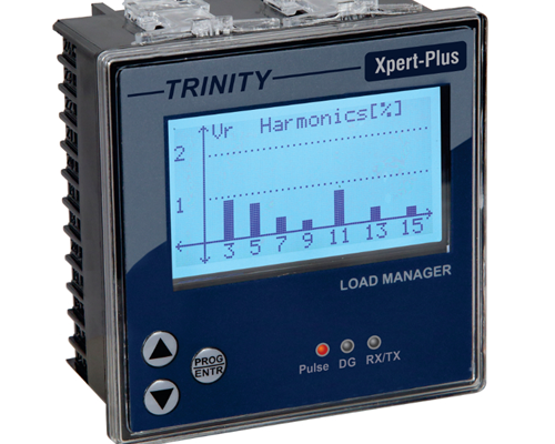
Trinity introduces the XPERT-PLUS, an easy-to-use, accurate and very versatile electrical power meter with innovative features, which is ideal for remote monitoring of electrical installations, Energy accounting and management, Demand Control, tenant billing and Power quality analysis.
The meter has three LEDs in the front, one to calibrate energies, one to indicate the status of RS485 communication and one to indicate load on DG.
The digital power meter GOBLIN PLUS is a micro-controller based unit which not only measures a host of electrical parameters to display them on a 480 x 272 (RGB) smart TFT display (Touch), but also acts as a comprehensive load managing device due to its four numbers of output relay contacts. These outputs are individually field programmable for both the parameter on which to generate alarm as well as the values on which to activate alarm and deactivate it. In addition to this flexibility in terms of load management, the meter also has RS485 port. RS485 supports MODBUS RTU protocol for connections to EMS/SCADA.
The meter has four LEDs in the front, two to calibrate energies, one to indicate the status of RS485 communication and one to indicate DG Status.
GOBLIN PLUS is a versatile meter, with all the features needed to implement a robust electrical load management system. It can be configured to suit most control and communication needs.

DRAF is an enclosed direct-on-line starter embedding AF technology. It is used for motor starting up to 7, 5 kW and 10 hp and complies with both IEC and UL/CSA standards. TF42 thermal overload relays for motor protection should be selected separately according to motor's nominal current.

TRINITY has a versatile range of Power Factor Correction relays suitable for all applications. These controllers are available in economy version with minimum features, intelligent models with advance control algorithm and also sub-second switching models with solid state outputs.
The entire series is economical user friendly and extremely reliable. Designs of these have been field proven for nearly fifteen years with more then 10000 units in service.

All models are single phase measurement. APFCR & NEWTON+ needs a CT input from the mains as well as from Capacitor Bank (For VAR mode operation). NANOVAR take only one current input from the mains, since they have only basic PF control option. Voltage input is taken from phase & neutral.
These controllers are user friendly and easy to program. There is no need to program C/K or bank sizes manually.
In VAR mode operation (Available in APFCR and NEWTON+) these controllers can sense as low as of 1% of the main load and take corrective action. PF control option requires minimum 2.5% of mains current for Newton+(Fast) and 6% of mains current for others.
The control parameter is VAR, and not PF. Target PF value is just used to calculate the capacitive VAR required to be added/removed to achieve the desired PF. e.g. If the target PF is unity, means that the target VAR in the system is zero. If system KVAR is 200 lagging, then the controller needs to add 200 KVAR of capacitor banks to reach zero VAR.
The calculation of the reactive power in the system is done by taking instantaneous samples of all voltage and current waveforms, in all four quadrants. These values are then subjected to DSP techniques to add a frequency independent 90° phase shift to current samples. The product of these voltage and current samples then generate signed VAR value.
VAR controller then takes into calculation the prevailing system KVAR, the prevailing bank KVAR and the bank sizes of each stage, and then switches ON/OFF the combination which is closest to the needed VAR.
This assumes a balanced loading of the electrical system. For unbalanced load conditions, Accuvar model is re-commanded.
| Feature | APFCR | NEWTON+(FAST) | Newton+ | NANOVAR |
|---|---|---|---|---|
| No. Of Stages | 4 to 16 | 6/8 optocouplers | 4/6/8 Relays | 4/5/6 Relays |
| ALARM on PF Value (Optional) | Y | Y | Y | - |
| Fast Switching | - | Y | - | - |
| Stage Indication | LED | LED | LCD | LCD |
| LC Display | 16 x1 | 16 x 2 | 16 x 2 | 16 x 1 |
| Intelligent Control | Y | Y | Y | - |
| Parameter | |||
|---|---|---|---|
| Type | Name | Statistics | |
| Input | Supply | One Phase and Neutral of 3P4W system | |
| Voltage | Direct Voltage Input: Up to 300V L-NBurden: 0.5 VA | ||
| Current | Secondary Current Input: 5A or 1A (To be specified at the time of Ordering) CT Ratio: Site Selectable (In APFCR & NEWTON+ only) Range of Reading: 0-5000A Burden: <1.0VA Overload: 5A CT = 6A RMS Continuous 1A CT = 1.2A RMS Continuous |
||
| Power Supply | Wide operating Voltage SMPS : 80 VAC - 480 VAC, 50-60 Hz | ||
| Output | Relay | Switching Voltage: Max. 250 VAC Switching Power: Max. 1000W Expected Mechanical Life: >10 X 106 switching operations Expected Electrical Life: > 4 X 10⁶ switching perations @ (Load = 200VA, Cosp = 0.5) |
|
| Optocoupler(Fast Newton+) | VCE(max)-40 VDC; Imax-30 mA | ||
| Measurement | True RMS Basic Parameters | Voltage(Volts L-N: VRN, VYN, VBN) | Accuracy: 0.5% of Reading |
| Current(Amps IR,IY, IB) | Accuracy: 0.25% of Reading | ||
| Capacitor Current | CT Ration: Site Selectable (In APFCR & NEWTON+ only) Accuracy: 1.0% of Reading |
||
| Power Factor | Accuracy: 1.0% of Reading (IPFI>0.5) Range of Reading: 0.05 to 1.00 Lag/ Lead |
||
| Miscellaneous | Dimensions | Bezel | 144 X 144 mm (APFCR), 96 X 96 mm (All other three models) |
| Panel Cutout | 138 X 138 mm (APFCR), 92 X 92 mm (All other three models) | ||
| Depth of installation | 55 mm | ||
| Operating temp | 10°C to 50° C | ||
| Weight | 0.730 Kgs (Approx.) for APFCR, 0.376 Kgs (Approx.) for all other three models | ||
| Min. Operating Current | 1% of CT primary in VAR mode, 2.5% in PF mode | ||
The ACCUVAR family of VAR controller consists of one product, with ACCUVAR as the base model. The ACCUVAR is Microcontroller based, with designs that have been field proven for more than fourteen years. The main features of the VAR controllers are:
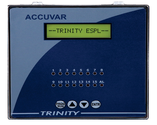
ACCUVAR is three phase measuring controllers, and hence need three CT inputs from the mains and also all the three phase and neutral connections. So, in addition to accurate control of VAR, this model also provides comprehensive electrical measurement. The parameters measured and displayed (depending on model selected ) are all voltages, currents, power factor, all powers and all energies, average PF maintained since last reset and THD figures for voltages and currents.
ACCUVAR has an autosense feature, which senses the sizes of the capacitor banks connected on each stage automatically. No need to programme C/K or bank sizes manually.
Since there is no fixed sequence of switching capacitors, if very small capacitor banks are connected, this controller senses down to 1% of the main load and takes corrective action.
The control parameter is VAR, and not PF. Target PF value is just used to calculate the capacitive VAR required to be added/removed to achieve the desired PF. e.g. If the target PF is unity, means that the target VAR in the system is zero.
If system KVAR is 200 lagging, then the controller needs to add 200 KVAR of capacitor banks to reach zero VAR.
The calculation of the reactive power in the system is done by taking instantaneous samples of all voltage and current waveforms, in all four quadrants. These values are then subjected to DSP techniques to add a frequency independent 90° phase shift to current samples. The product of these voltage and current samples then generate signed VAR value. VAR controller then takes into calculation the prevailing system KVAR, the prevailing bank KVAR and the bank sizes of each stage, and then switches ON/OFF the combination which is closest to the needed VAR.
| Feature | Description | ACCUVAR(Opto-isolators) | ACCUVAR |
|---|---|---|---|
| No.Of Stages (Relay outputs) | 5A@ 230 VAC, Resistive load. | 15 | 15 |
| ALARM on PF Value | Y | Y | |
| Rs 485 Port (Option) | Supporting MODBUS-RTU protocol, for integration with SCADA/EMS | Y | Y |
| Fast Thyristor Outputs Switching | - | Y | - |
| LED Stage Indication | Y | Y | |
| LC Display | 16x1 | 16x 1 |
| Parameter | |||
|---|---|---|---|
| Type | Name | Statistics | |
| Input | Supply | Three Phase and Neutral of a 3P4W system | |
| Voltage | Direct Voltage Input : Up to 300 V L-N Burden: 0.5 VA |
||
| Current | Secondary Current Input: 5A or 1 A (To be specified at the time of ordering) Range of Reading: 0 - 5000A Burden: < 1.0 VA Overload: 5A CT = 6A RMS Continuous 1A CT = 1.2A RMS Continuous |
||
| Power Supply | Self Powered from mains Wide operating Voltage SMPS: 80 VAC - 480 VAC, 50-60 Hz |
||
| Output | Relay | Switching Voltage: Max. 250 VAC Switching Power: Max 1000W Expected Mechanical Life: >10 x 106 switching operations Expected Electrical Life : >4 x 10⁶ switching operations @ (Load = 200 VA, CosØ = 0.5) |
|
| Measurement | True RMSBasicParameters | Voltage(Volts L-N: VRN, VYN, VBN) | Accuracy: 0.5% of Reading |
| Current(Amps IR, IY, IB) | CT Ratio: Site Selectable Accuracy : 0.5% of Reading |
||
| Capacitor Current | |||
| Line Frequency | 45 to 55 Hz, Accuracy : 0.3% of Reading | ||
| Power | Active Power (P) | Accuracy : 1.5% of Reading (For IPFI>0.9) | |
| Reactive Power (Q) | Accuracy : 2.0% of Reading (Between 0.5 Lag to 0.8 Lead) | ||
| Apparent Power (S) | Accuracy : 1.0% of Reading | ||
| Power Factor | Accuracy : 1.0% of Reading (IPFI>0.5)Range of Reading : 0.05 to 1.00 Lag/ Lead | ||
| Energy | Total Active Energy (KWh) | Range of Reading : 0 to 99999999.9 KWh Accuracy : 0s as per IS 13779 |
|
| Total Apparent Energy (KVAh) | Range of Reading : 0 to 99999999.9 KWh Accuracy : 1.0% of Reading |
||
| Misc. | Cap. Bank KVAR | ||
| Run time | |||
| Miscellaneous | Dimensions | Bezel | 144 X 144 mm |
| Panel Cutout | 138 X 138 mm | ||
| Depth ofinstallation | 55 mm | ||
| Depth ofinstallation | 76 mm with Bezel | ||
| Operating temp | 10° C to 50° C | ||
| Weight | 0.82 Kgs (Approx.) | ||
| Min. Operating Current | 1% of CT primary | ||
The relay is meant for flush mounting in a panel for connection to the electrical system.The relay is the ‘intelligence’ which controls the automatic system for correction of the power factor. It senses the power factor by taking the ratio of the KW and the true rms KVA of the system, for any phase to neutral or phase to phase connections of the three phase electrical system.
This means that phase to neutral or phase to phase are connected to the meter as voltage inputs and current of the same phase or different phase as current input. For correct operation of the relay, however there are some minimum requirements should be met.
Unless the various points in the system which are mentioned below are correctly setup, proper operation of the relay cannot be expected.

| Parameters | |||
|---|---|---|---|
| Type | Name | Statistics | |
| Input | Power Supply | Auxiliary Supply : 80 - 500 VAC, 50-60 Hz. | |
| Voltage | Direct Voltage Input : 50-300V L-N & 50-500V L-L Burden : 0.5VA |
||
| Current | Secondary Current Input : 5A or 1A (Site Selectable) CT Ratio: Site Selectable Range of Reading : 5 - 9995A Burden : < 1.0VA Overload: 5A CT = 6A RMS Continuous 1A CT = 1.2A RMS Continuous |
||
| Output | Relay | Switching Voltage : Max. 230 VAC Switching Power: Max. 1000W Expected Mechanical life : >10 x 10^6 switching operations Expected Electrical life:>4 x 10^6 switching operations@(Load = 200VA, Cosφ=0.5) |
|
| MEASUREMENT | True RMSBasicParameters | Capacitor Current | CT Primary : Site Selectable Range of reading : 5 – 9995A Accuracy : 1.0% of Reading |
| Power Factor | Accuracy : 1.0% of Reading (IPFI ≥ 0.5) | ||
| MISC. | Dimensions | Bezel | 144 X 144 mm |
| Panel Cutout | 138 X 138 mm | ||
| Depth of installation | 55 mm | ||
| Operating temp | 10°C to 50°C | ||
| Weight | 0.560 Kg. (Approx.) | ||
| Min. Operating Current | 5% of CT Primary in FIFO/SFIFO mode | ||
The digital power meter VAR-Z16 is a micro-controller based unit which not only measures a host of electrical parameters to display them on a 128 X 64 graphical backlit LCD, but also acts as a comprehensive power factor controlling device due to its sixteen numbers of output relay contacts. There are two alarm relays. These two alarm outputs are individually field programmable to generate alarm as well as the values on which to activate alarm. In addition to this flexibility in terms of power factor controlling, the meter also has one serial port: RS485, supports MODBUS RTU protocol for connections to EMS/SCADA.
The unit is meant for use in three phase four wire systems. The installation type, CT ratios are site selectable.
VAR-Z16 is a versatile meter with a robust electrical load measurement system and consists of all the features needed to implement. It can be configured to suit most control and communication needs.

| Parameters | |||
|---|---|---|---|
| Type | Name | Statistics | |
| Input | Supply | Three Phases and Neutral of a 3P4W system | |
| Voltage | Direct Voltage Input : Up to 500V L-L, Up to 300V L-N Burden : 0.5VA |
||
| Current | Secondary Current Input: 5A or 1A (Site Selectable) CT Ratio : Site Selectable Range of Reading : 5 – 5000A Burden : < 1.0VA Overload : 5A CT = 6A RMS Continuous 1A CT = 1.2A RMS Continuous |
||
| PowerSupply | Auxiliary Supply: 90 - 470 VAC, 50-60 Hz drawn from 3 phase connection done for measurement. | ||
| Output | Relay | 16 Relays contact with Common for PF Controlling. 2 Relays contact with Common for ALARM Indication. Switching Voltage : Max. 230 VAC Switching Power : Max. 1000W Expected Mechanical Life : >10X106 switching operations Expected Electrical Life : > 4X10⁶ switching operations @ (Load = 200VA. Cosj = 0.5) |
|
| MEASUREMENT | True RMSBasicParameters | Voltage(Volts L-N & L-L) | VL-N Accuracy : 0.5% of Reading VL-L Accuracy : 1.0% of Reading |
| Current(Amps IR, IY, IB) | Accuracy : 0.25% of Reading | ||
| Line Frequency | 45 to 55 Hz, Accuracy : 0.3% of Reading | ||
| Power | Active Power (P) | Accuracy : 1% of Reading(For IPFI>0.5) | |
| Reactive Power (Q) | Accuracy : 1.5% of Reading(Between 0.5 Lag to 0.8 Lead) | ||
| Power Factor | For Individual phases and System. Accuracy : 1.0% of Reading (IPFI ≥0.5) Range of Reading : 0.05 to 1.00 Lag/Lead |
||
| Energy | Phase wise Active Energy (KWh) | Range of Reading : 0 to 999999999.9 KWh Accuracy : Class 0.5 as per IS14697 |
|
| Phase wise Reactive Energy (KVARh – LAG & LEAD) | Range of Reading : 0 to 999999999.9 KVARh Accuracy : Class 1.0 |
||
| PowerQuality | 3rd to 15th Harmonics(Odd) for all Voltages with THD | ||
| 3rd to 15th Harmonics(Odd) for all Currents with THD | |||
| MISC. | Dimensions | Bezel | 144 X 144 mm |
| Panel Cutout | 138 X 138 mm | ||
| Depth of installation | 55 mm | ||
| Display | 128 X 64 graphical Backlit LCD | ||
| Operating temp | 10°C to 50°C | ||
| Weight | 0.60 Kgs (Approx.) | ||
| Operating Current Range | 0.4% to 120% of CT primary | ||
| RS485 | Modbus-RTU protocol | ||
The AMF relay is a micro-controller based unit which automates generator start and stop actions during mains failure by controlling both mains and generator contactors. It also measures voltage, current and frequency and displays it on a 20 x 4 LCD. It has 12 LEDs for different indications. All programmable parameters are password protected and are stored in a non volatile memory and thus all information is retained in the event of complete loss of battery power. AMF can be operated in "AUTO","QAUTO" (Quick Auto) or "MANUAL" mode. The unit features a non-erasable incremental "DG run hour" and "maintenance hour. This unit is meant for use in three phase four wire systems. The "CT ratio" is site selectable. The unit is powered by a wide input (9-36VDC) power supply, which makes it suitable for both 12V and 24V battery systems.

| Parameter | |||
|---|---|---|---|
| Type | Name | Statistics | |
| Input | Three Phases and Neutral of a 3P4W | ||
| Voltage | Direct Voltage Input: Up to 300V L-N Burden: 0.5VA |
||
| Current | Secondary Current Input : 5A or 1A (Site Selectable) CT Ratio : Site Selectable Range of Reading : 5 – 5000A Burden : < 1.0VA Overload : 5A CT = 6A RMS Continuous 1A CT = 1.2A RMS Continuous |
||
| Power Supply | 9-36V DC | ||
| Output | Relay | Six Relays(NO) Switching Voltage : Max. 250 VAC Switching Current : 6 A (Resistive load) Expected Mechanical Life : >1X10 switching operations Expected Electrical Life : > 5X10 switching operations |
|
| Measurment | True RMSBasicParameters | Voltage (Volts L-N ) | VL-N Accuracy : 1.0% of Reading |
| Current(Amps IR, IY, IB) | Accuracy : 0.25 % of Reading | ||
| Line Frequency | 45 to 55 Hz, Accuracy : 0.3% of Reading | ||
| Dimensions | Bezel | 144 X 144 mm | |
| Panel Cutout | 138 X 138 mm | ||
| Depth of installation | 55 mm | ||
| Display | 20 X 4 Backlit LCD | ||
| Operating temp | 10°C to 50°C | ||
| Weight | 0.58 Kgs (Approx.) | ||
| Operating Current Range | 0.4% to 120% of CT primary | ||
You can check the technical specifications and features from the button given and download catalog.

You can check the technical specifications and features from the button given and download catalog.
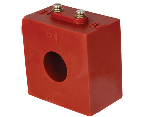
11 KV CT/PT

Remote Energy Management Solution enables to Monitor, Manage, analysis and Control Multi-Location Energy Operation.

You can check the technical specifications and features from the button given and download catalog.